Remote-Controlled RC Car
A rear-wheel-drive RC F1-style car built end to end — custom-printed circuit boards, a brushless drivetrain, and Ackermann steering.
Built with Sarah Rodrigues and Helen Chang for a term-long Projects in Engineering course — the goal was a remote-controlled, F1-style race car to run on a track we designed ourselves.
Overview
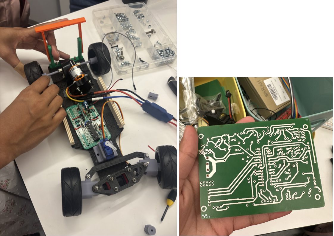
A ground-up remote-controlled car that lives at the intersection of electrical and mechanical design. It’s driven by a brushless motor for rear-wheel drive and a servo on the front wheels for steering — and nearly every part, from the circuit boards to the chassis, was designed and fabricated by hand.
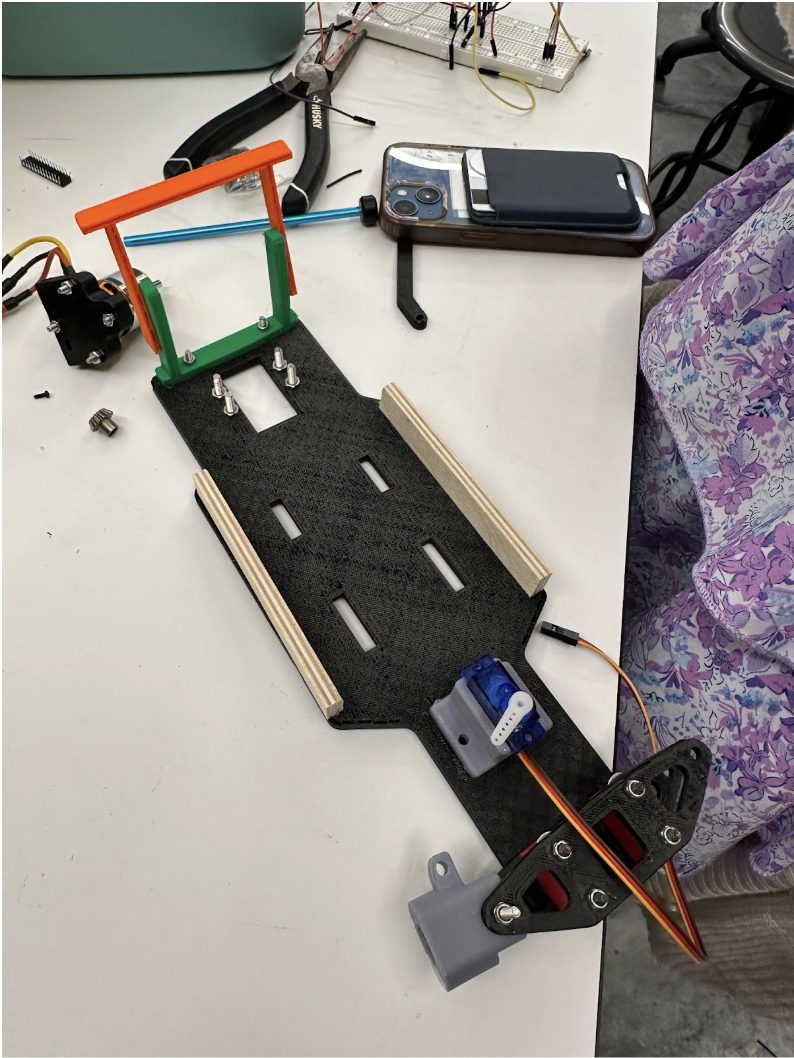
The electrical side
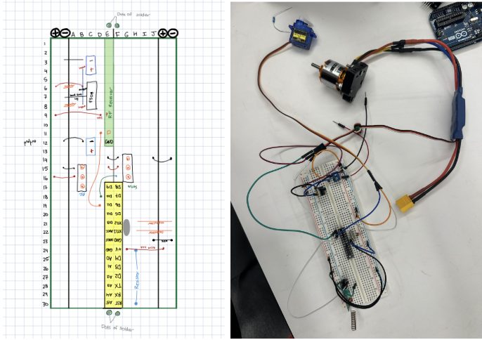
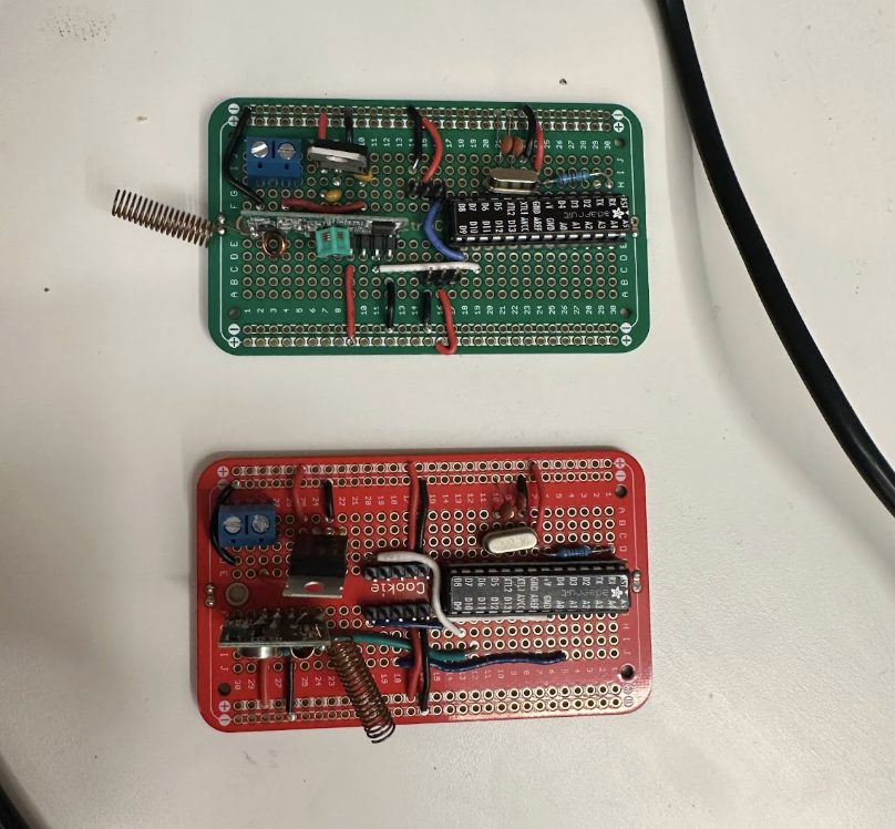
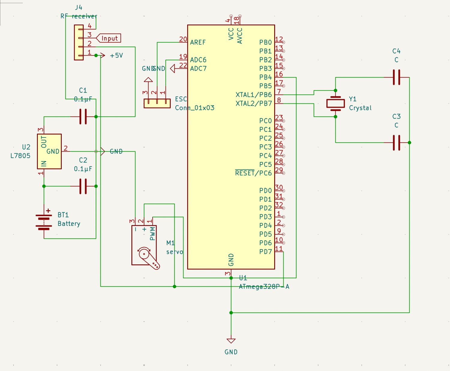
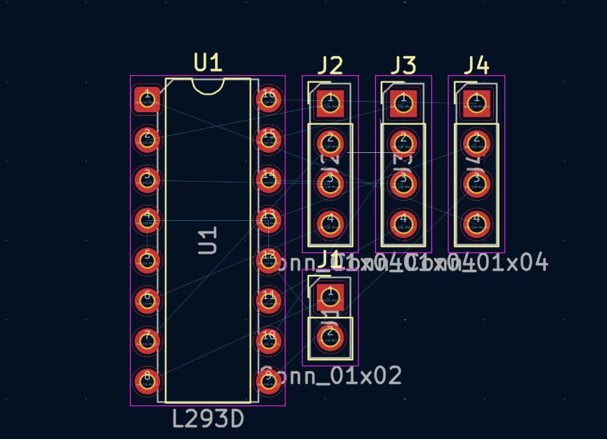
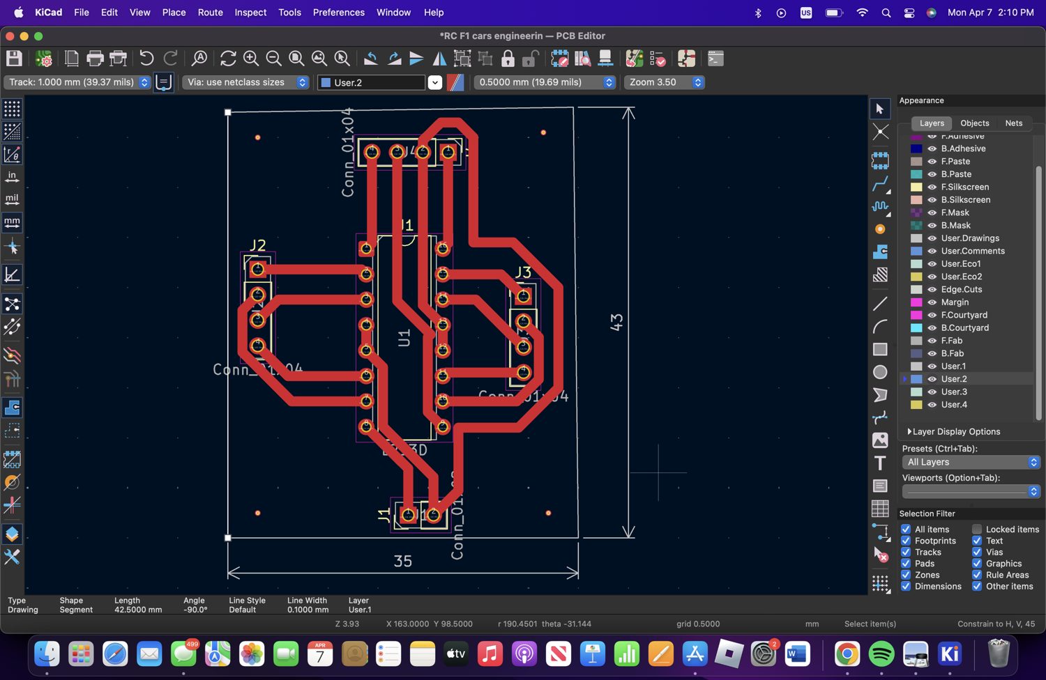
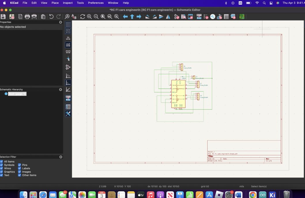
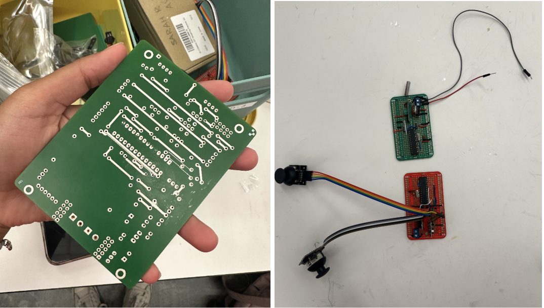
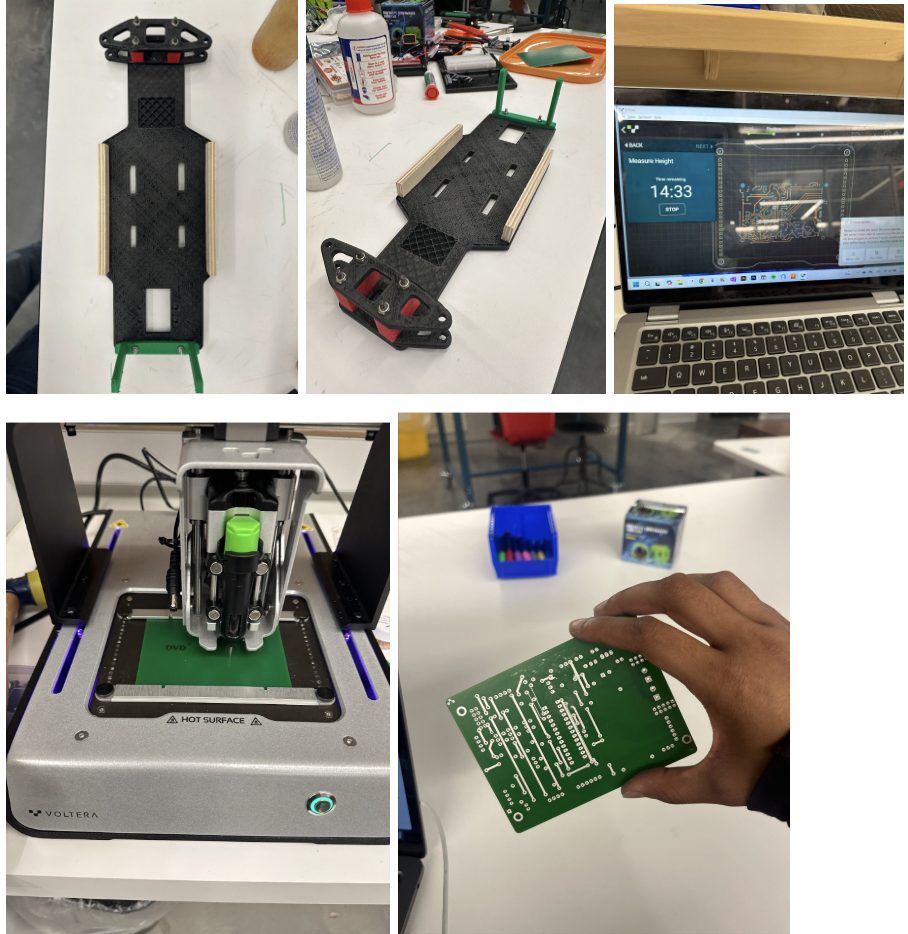
I got access to a Voltera circuit-board printer, which let us design, print, and test our own PCBs rather than relying on off-the-shelf boards. I designed the board in KiCad — which was a real learning curve: beyond wiring the schematic and getting the pinouts right, I hadn’t realized that assigning footprints and laying out the physical board from the parts was its own whole stage of the process.
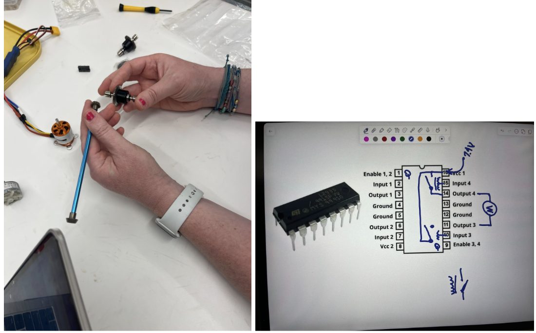
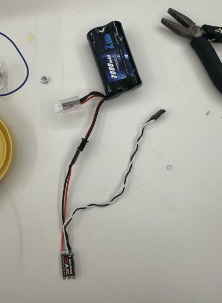
The drivetrain runs on a brushless motor (rear-wheel drive) through an ESC, controlled alongside the steering servo from a microcontroller. Researching brushless motors and the ESC was eye-opening — I’d naively assumed a motor was a one-size-fits-all part, and comparing motor types, batteries, and speed controllers taught me how they actually work.
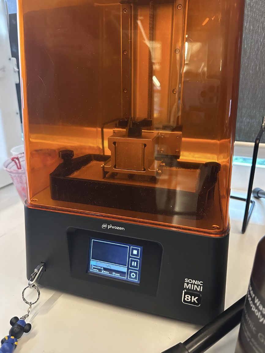
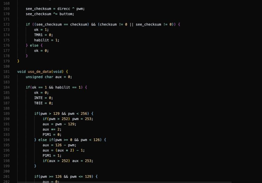
Debugging the radio control was one of the hardest parts: I tried three different approaches to a stubborn communication problem before finally getting it working by editing the RadioHead command in terminal. We also pushed into tools that were new to all of us — a resin printer and the Voltera — which meant a lot of trial, error, and correcting.
The mechanical side
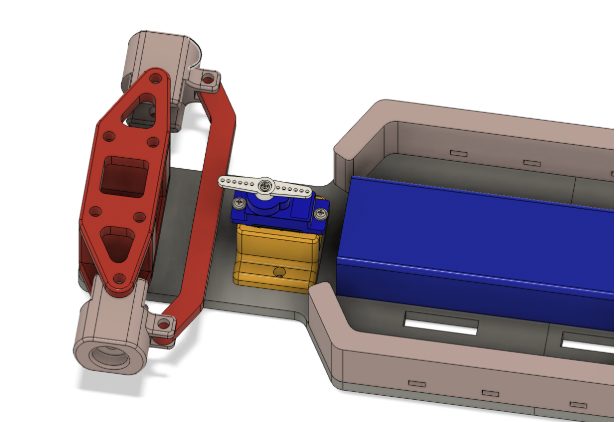
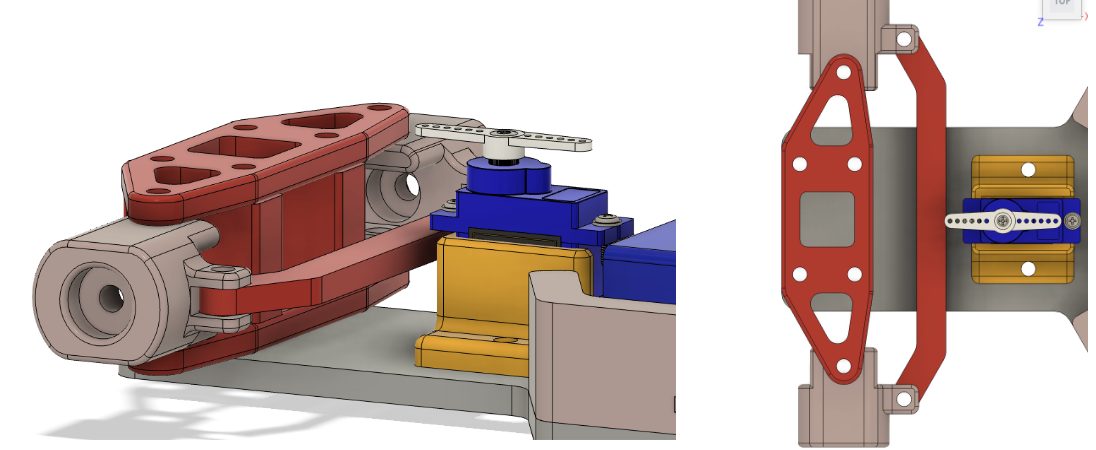
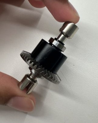
The car uses Ackermann steering — the geometry that lets the inner and outer front wheels turn at slightly different angles so all four wheels trace clean arcs through a turn. Getting from that geometry to a working linkage was the toughest mechanical challenge, and it gave me a new appreciation for how many parts hide beneath the “looks” of a car: axles, knuckles, differentials, and the ESC, not just the wheels and rear wing.
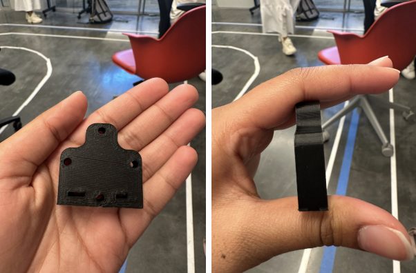
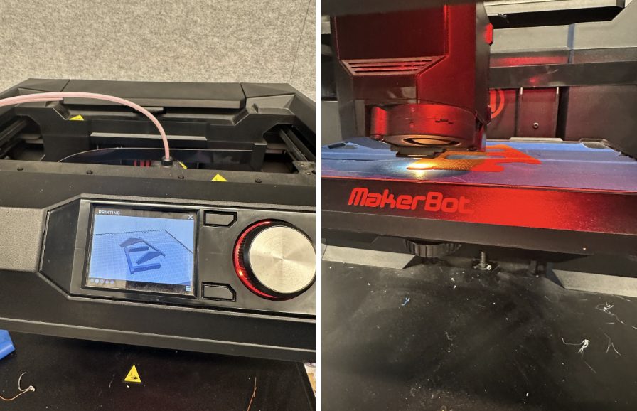
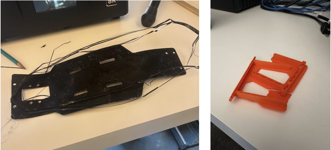
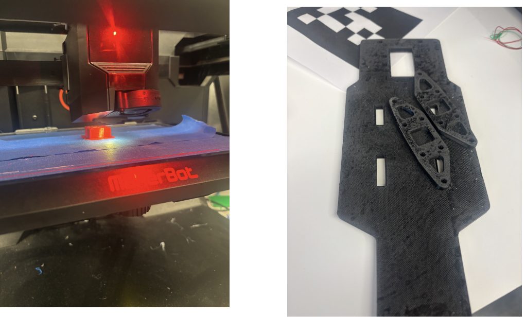
Structural and custom parts were 3D printed, modeled in Autodesk Fusion 360 — and printing was its own iterative battle, swapping printers, slicing and re-arranging the print file, and experimenting with support types until the parts came out clean.
What I learned
- Designing, printing, and debugging our own circuit boards on the Voltera + KiCad.
- Driving a brushless motor + ESC and a steering servo from a microcontroller.
- Translating Ackermann steering from geometry into a working linkage.
- Coordinating three subsystems — code, circuit, and chassis — so the pins, the wiring, and the physical space all agreed.
- Iterating relentlessly between CAD, print, and physical test, and learning new tools (resin printer, Voltera) under real time pressure.
If we had two more weeks: clean up the Ackermann steering so it works and looks the part, and finish migrating the soldered board to a Voltera-printed PCB — the plan from the start.
Build log
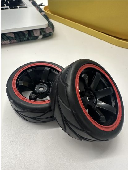
The build, week by week — circuit design, 3D prints, chassis, and assembly. Use the arrows to step through:
📓 Origins / build log: the full week-by-week process — every prototype, failure, and fix — lives on our Projects in Engineering blog.