CAD Bridge (FEA)
A laser-cut MDF bridge designed in Fusion 360 and iterated dozens of times against FEA stress tests to carry a cinder block.
Built with Sarah Rodrigues for Intro to Mechanical Engineering (Ms. Selan) — the first project of the term, meant to get us fluent in Fusion: design a bridge that could carry a 40-lb cinder block, then fabricate it from laser-cut 1/8-inch MDF.
The brief came with real constraints:
- One 12″ × 24″ sheet of 1/8″ MDF — nothing else.
- No glue, tape, or fasteners of any kind. It had to hold together on friction and geometry alone.
- The block may only rest on the cross members, not on the side profile.
- No component may have a horizontal length greater than 18 inches.
- The bridge must span a 26″ gap.
- Make it as light as possible.
Sketch → Fusion → FEA
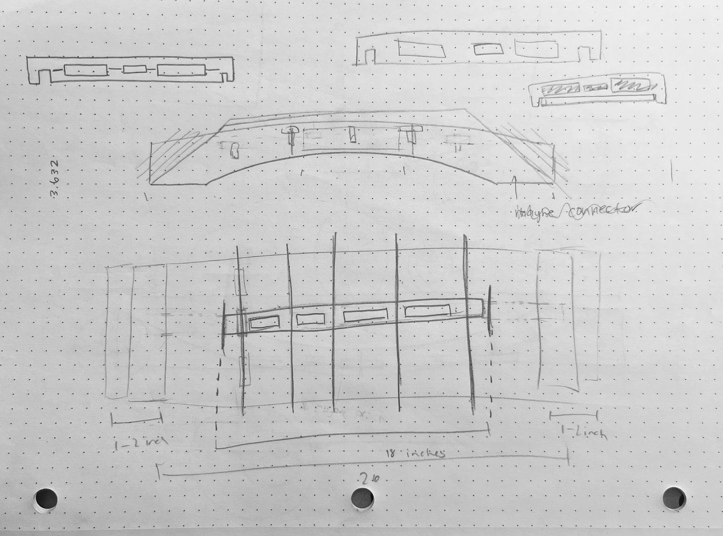
We started in the dot notebook, sketching how we wanted the bridge to look. The idea: use arcs and angles to tie the side components together and push the cinder block’s load into the parts of the structure we thought were strongest, so it wouldn’t crack.
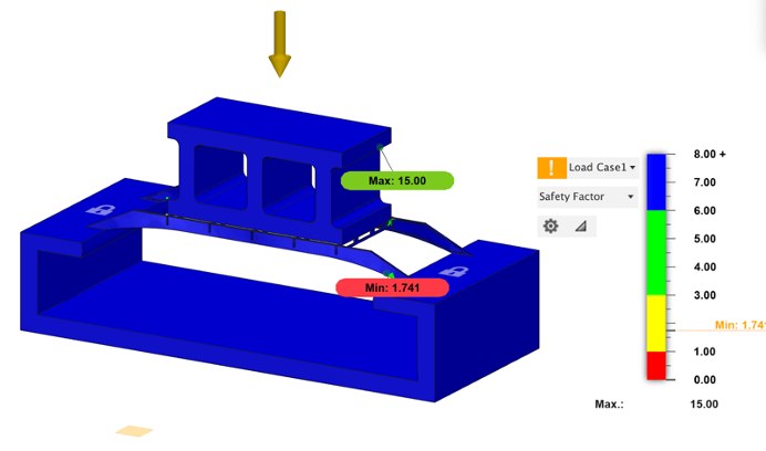
From the sketch we moved into Fusion 360 — a side profile, extruded, with cross-beams added to make Design 1. Then came round after round of FEA stress testing to check our safety factor and see how the bridge was projected to hold up. We used each result to trim material and make the next version lighter.
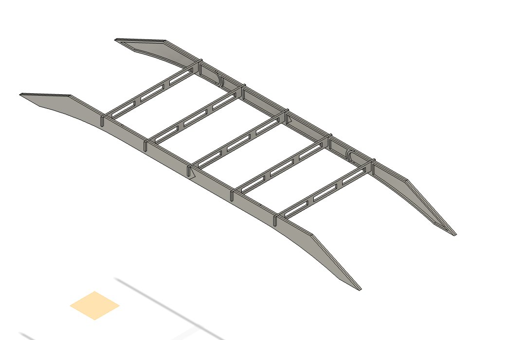
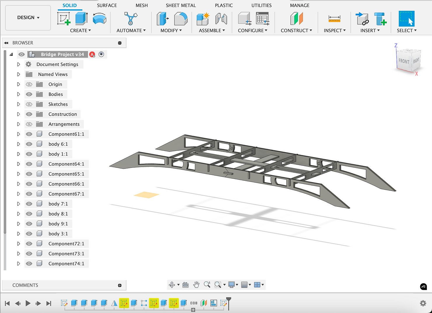
We changed the design something like fifteen times — the Fusion file climbed to v34 — so the first and last bridges look quite different. This was the project that taught me how much iteration matters: after each change I’d spot something else to refine, and after enough FEA I could look at a bridge and pretty much feel where it would be weak or strong before running the test. It was also my first time using the practical, simulation side of Fusion — until then I’d only used it for aesthetic modeling.
Stress testing, version by version
Five designs made the cut as documented FEA milestones. Each one traded a little mass against a target safety factor, using the previous simulation to decide exactly where to add or remove material.
Version 1 — 5.187 oz. Design 1, straight off the sketch. The deformation plot showed the side pieces that form the arch were stronger than they needed to be, so we planned to hollow out their outer layers to shed weight — while shrinking the hole in the inner layer of the end/support pieces, where the sim showed a weaker, more stressed composition under the block.
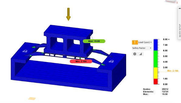
Version 2 — 4.521 oz, min. safety factor 2.198. Hollowing worked: nearly 0.7 oz lighter with plenty of margin. But a band of stress showed up near the arches, so the next move was to add an extra arch on the outer layer where the inner-layer arch was reading green/yellow, to feed more support into the area carrying most of the block’s weight.
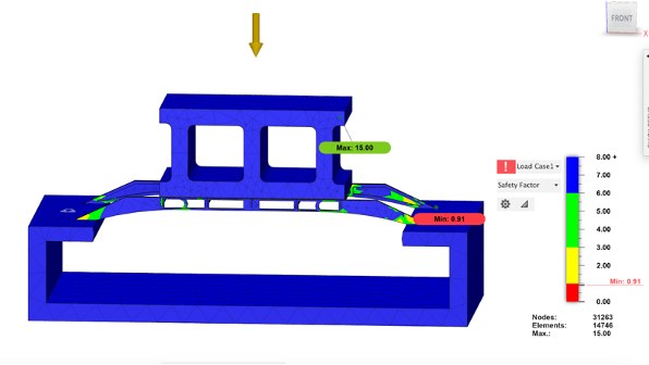
Version 3 — 4.567 oz, min. safety factor 0.91. The safety factor dropped sharply — because this test was far more honest. Earlier versions assumed most part contacts were bonded; here we changed every contact that could be to sliding, which is how the pieces actually behave with no glue or fasteners. The lower number reflected reality, not a worse bridge. It told us to “un-hollow” the inner-layer end pieces for support, push the deck’s curve farther out, and trade the outer-layer arcs back to solid wood (keeping them on the inner layer) — heavier, but getting the stress out of the yellow was worth it.
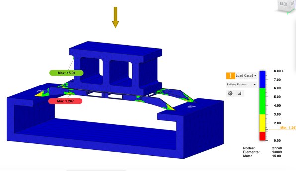
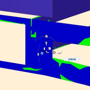
Version 4 — 5.592 oz, min. safety factor 1.267. With the ends reinforced, the safety factor recovered. To find what to trim next we used Fusion’s Slice Plane — effectively a CAT scan of the internal stress — and, with Ms. Selan’s help, reduced the size of the end horizontal cross pieces to bulk up the wood and support underneath where it was reading yellow.
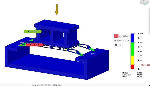
Version 5 — 4.862 oz, min. safety factor 0.698 (final). Last step was calibration: we measured the actual MDF with a caliper and set the Fusion thickness parameter to 0.1230″ to match the real board. The safety factor looks alarming, but after talking it through with Ms. Selan we realized the simulation wasn’t loading all of the crossbars — it ignored the middle horizontal pieces that would share the block’s force in real life — so we expected the true, more evenly distributed load to give a meaningfully higher factor.
From first to last we hollowed out much more of the side pieces (little stress there) while keeping solid wood at the table-contact edges (low safety factor there), for a net weight cut of ~0.325 oz. The final design carried a relative safety factor of 1.719 in Fusion — comfortably expected to hold.
Building it
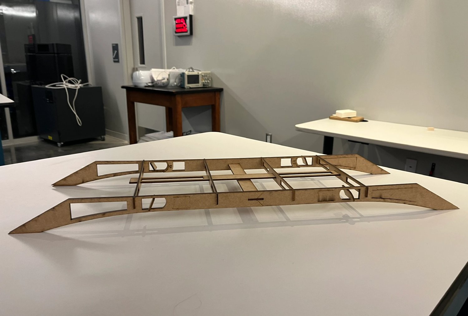
We laser-cut the bridge from MDF. Our first cut didn’t hold — the MDF was slightly too thick for the joint clearances, so the pieces wouldn’t stay together (a good lesson in designing for real material tolerances). Assembly of the final version went smoothly, and — satisfyingly — the bridge supported its own shape with no single piece spanning the full 26″ gap, exactly as the no-fasteners, 18″-max-component constraints forced us to design it.
How it did
The geometry was sound, but the material felt flimsier in hand than it did in simulation — and under load the bridge cracked down the arcs on the sides. Watching it fail, Sarah and I already had concrete ideas for how we’d reinforce it next time. For a first structural project, learning to read a stress plot and iterate against it — bonded vs. sliding contacts, slice-plane analysis, calibrating the model to the real material — mattered more than the final result.